Get in touch with UDTECH Company


Updated September 2026
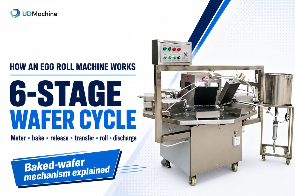
"How does an egg roll machine work" is answered by following the material through six functions: metering, baking, release, transfer, rolling, and discharge. The first job is to identify the food. This guide covers an industrial machine that turns liquid batter into a thin baked wafer and rolls that wafer while it is still formable. It does not cover a filled, fried spring roll or a countertop appliance that cooks whole eggs.
Some product listings call the same industrial equipment an egg roll maker. In this food production process, flour-based batter becomes a crisp or crispy wafer through baking and hot forming.
Direct answer: An automatic egg roll machine meters batter onto a heated moving surface, bakes the thin layer, releases its edge, transfers the hot wafer, wraps it around a forming element, and discharges the shaped roll. Those are six functions, not necessarily six separate stations. Drives, sensors, controls, and protective devices coordinate the cycle.
Input stateFlowable batter
Core changeLiquid → baked sheet → tube
Six functionsMeter, bake, release, transfer, roll, discharge
Important limitHardware can serve more than one function
This is a baked-wafer timing-sequence explainer, not a buying guide. It doesn’t publish capacity, model specifications, prices, recipes, maintenance instructions, troubleshooting steps, or quality-control settings. For product-family context, see the batter-fed and wrapper-fed automation overview.
Within a wafer-roll production line, a machine maker may use stainless steel around food-contact zones and conventional steel in the supporting frame. Those material choices matter to construction, while cycle efficiency still depends on uniform batter delivery, controlled heat contact, and the geometry of each baking mold or plate.
Which Egg Roll Machine Does This Explanation Cover?
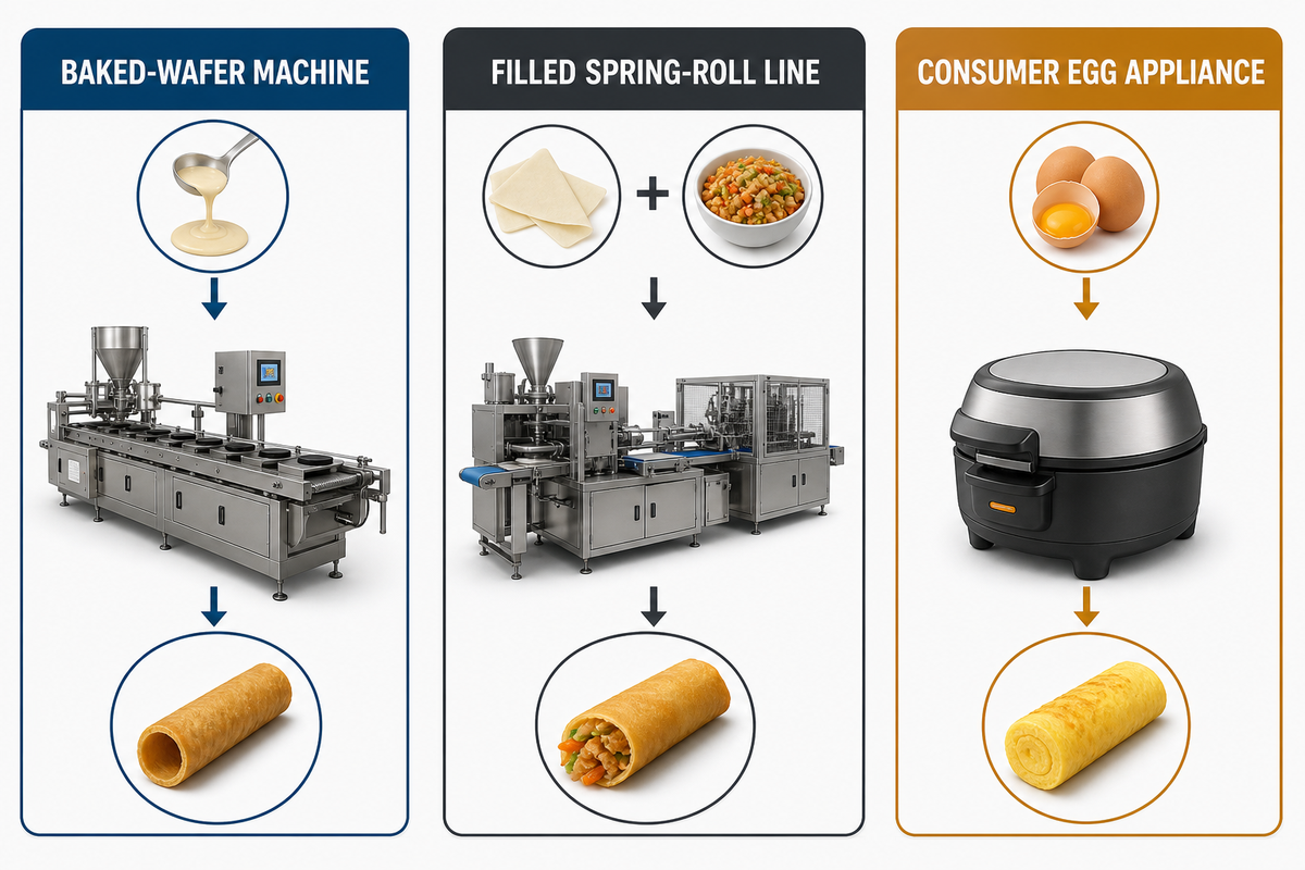
Here, “egg roll” means a crisp, tubular wafer made from batter on a heated surface. That definition matters because the same English words lead to several unrelated machine families in search results. A product-family mismatch creates a practical risk because a wrapper-and-filling line does not follow the heated-wafer path explained here.
Why keep the scope this narrow? Our live result set contained 2 guide or article pages among 7 organic results, a 28.57% informational share. Across the 36-keyword intent set, 25 terms were classified as transactional and 3 as commercial, so 77.78% pointed away from a mechanism-only answer. That is why this article keeps prices, capacity selection, maintenance, and supplier comparison outside the six-stage explanation.
| Machine family | Starting material | Defining operation |
|---|---|---|
| Baked-wafer egg roll machine | Liquid or flowable batter | Bake a thin sheet, then roll it while hot |
| Filled spring-roll line | Wrapper dough or a prepared wrapper plus filling | Sheet, fill, fold, and close before a later cooking step |
| Consumer egg appliance | Whole egg or egg mixture | Cook an egg portion rather than form a wafer tube |
The distinction is visible in machinery records. The text of published wafer-roll machine application CN119073336A describes batter coating, baking, scraper release, forming, and cutting.
By contrast, filled-roll equipment handles a wrapper and filling. We’ll therefore follow only the baked-wafer path below.
How Does an Egg Roll Machine Work? The Six-Stage Answer
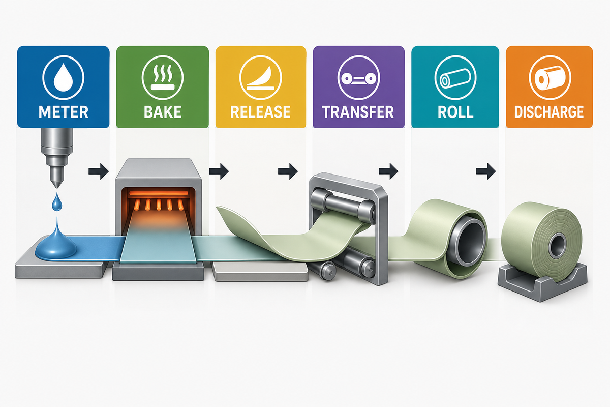
The clearest explanation follows the material, not a supplier’s component names.
Batter becomes a supported thin layer, then a baked sheet, then a free hot wafer, and finally a formed roll. Six functional labels make those changes easy to locate.
The common risk is a wrong station count because shared hardware can change the material state across a functional boundary.
Stage-to-Mechanism Locator: Find the material first. Liquid before the hot surface points to metering. The flat layer on that surface points to baking. Its lifting edge marks release. Once free, the moving sheet marks transfer. Wrapping around a former marks rolling. Departure from the former marks discharge.
- Meter: deliver a timed amount of batter to the receiving surface.
- Bake: support and heat the thin layer long enough to create a coherent wafer.
- Release: separate an edge or the whole sheet from the baking surface.
- Transfer: move and orient the hot wafer toward the former.
- Roll: wrap the flexible sheet around a rod, mandrel, roller, or forming assembly.
- Discharge: let the formed roll leave the former and enter the outgoing path.
For configured models, commercial specifications, or quotation intent, use the UDTECH commercial machine configuration brief. The six-stage explanation below remains supplier-neutral except where a named source documents one specific design.
Don’t read that list as a drawing of six isolated mechanisms.
A Nestlé-supported study using wafers made in a Haas single-plate oven reports that the engraved plate surface helps batter spread as the hot plates close and also helps later removal by reducing sticking. One physical feature can therefore influence metering, heat contact, and release. The open-access study is a useful reminder that the six stages are a functional map, not a universal station count.
Stage 1: How Does the Machine Meter and Deposit Batter?
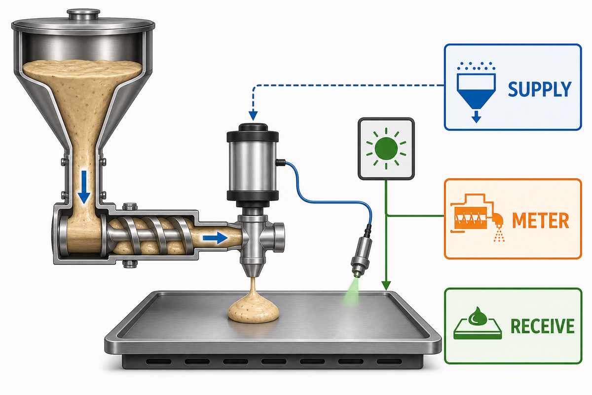
The first function turns a batter supply into a deposit that arrives when the receiving surface is ready. Depending on the design, a hopper, dosing pump, valve, coating plate, or another delivery arrangement may be used. “Automatic feeding” is only a label until the trigger and physical action are identified.
| Function | Question it answers | Possible design-family example |
|---|---|---|
| Supply | Where is batter held before a cycle? | Hopper or feed vessel |
| Meter | What creates a controlled portion or flow? | Dosing pump or coating device |
| Start/stop | What opens or closes the delivery path? | Valve, suck-back, or timed actuator |
| Receive | What confirms that the hot surface is in position? | Mould-arrival or position signal |
Nestec’s EP2105051B1 depositing record gives one concrete example: feed is coordinated with the arrival of a baking mould, and its embodiments discuss dosing and flow shut-off. Another machine may spread batter on a moving drum. The transferable idea is timed delivery to a prepared receiving surface, not one compulsory pump or nozzle.
Deposition also need not encompass all spreading. When plates close, their geometry can continue distributing the batter. That overlap is why this guide names functions rather than assuming every stage has a clean mechanical boundary.
Stage 2: How Do the Baking Plates Carry and Heat the Batter?
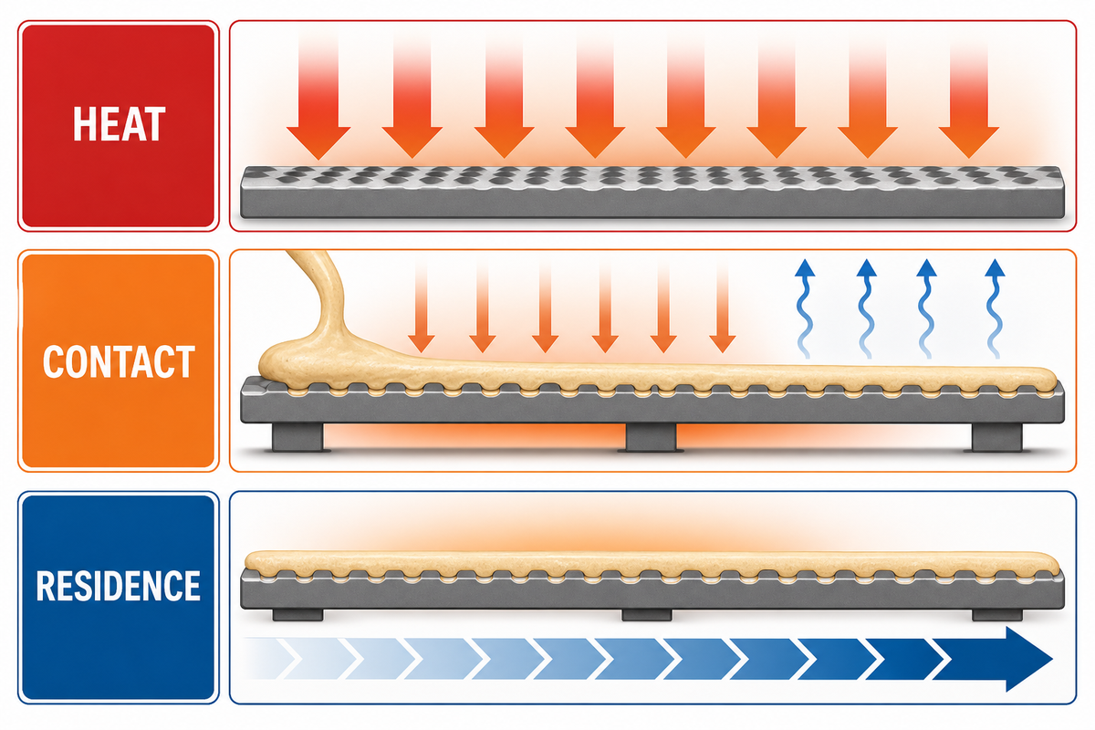
Once the batter reaches a hot surface, the machine must support the thin layer while heat transforms it into a peelable sheet. Motion and heating belong in the same explanation because motion defines how long the material remains in the heating path.
Energy-and-motion view: The heater supplies energy; the plate, mould, wheel, or drum creates contact and carries the batter; the drive establishes the path; and the path plus speed or index timing establishes the residence interval. Moisture leaves as structure develops.
One peer-reviewed tunnel-oven study follows biscuits on a metal rack conveyor and identifies temperature, humidity, air speed, and heat transfer as critical baking variables. This study relates to biscuits rather than this exact machine, so it explains the general heating path, not a wafer setpoint. See the open-access oven-monitoring paper.
Speed therefore helps define effective cooking time, while batter distribution and heat contact help the layer bake evenly. This relationship explains the variables without assigning a universal recipe or setpoint.
The machine architecture alters how that interval occurs. Moving plates may pass through a heated path, indexed layouts may step and hold between positions, and a continuous design may bake a strip on a revolving drum. The Haas US6254916B1 record, for example, illustrates fluid wafer dough baked as a continuous strip on a hot revolving surface.
Plate characteristics can also cross stage boundaries. Baking-plate engravings (reedings) may influence spreading, contact geometry, sticking, and separation in the same close-and-bake event. For a broader perspective on the physical process without purchasing or modeling claims, consult the baked wafer process guide.
Stage 3: How Does the Baked Wafer Release from the Plate?
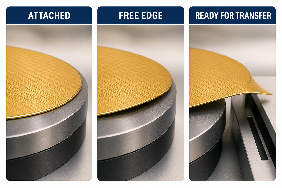
Release transitions the sheet from “fixed to the baking surface” to “free for transfer.” The shared function is separation, but the relevant hardware varies. Scrapers can lift an edge from a baking wheel; removal blades can peel a continuous strip from a drum; plate geometry may reduce sticking before either action begins.
The label non-stick should not be treated as a universal mechanism. Surface finish, coating, plate geometry, product formulation, and the release device can all affect separation.
A release failure can delay the transfer because the next mechanism cannot act until a free edge or sheet is available.
| What stays the same | What may change | Evidence boundary |
|---|---|---|
| A free edge is created | Scraper, blade, lift, or plate opening | Name the cited design |
| The sheet leaves the hot surface | Continuous peel or discrete pick-up | Do not call one layout universal |
| The wafer remains unrolled at first release | The same component may begin guiding it | Separate functions, not necessarily actuators |
In published application CN119073336A, a scraper mechanism removes the baked skin from a wheel before forming. In the Haas US6254916B1 record, a removal blade separates the hot strip and slopes toward the winding area. These patent records support two mechanism families, not a promise that every automatic egg roll machine uses either exact layout.
Stages 4 and 5: How Is the Hot Wafer Transferred and Rolled?
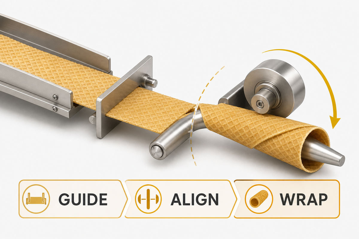
After release, the wafer must arrive at the forming station before it loses the pliability required for wrapping. Transfer moves and orients it. Rolling then curves the sheet onto a shaping element and establishes the overlap that creates a tube.
In supplier terminology, the forming machine may mean this wrapping assembly rather than a separate standalone machine. The functional boundary is the point where transfer ends and the hot sheet starts bending around an axis.
1 · Free the edge
The sheet stops being fully attached to the baking surface.
2 · Guide the sheet
A blade, guide, gravity path, pick-up, or transfer element aims it toward the former.
3 · Capture and wrap
A mandrel, rod, roller pair, or forming assembly bends the hot sheet into a tube.
The continuous-drum patent offers a particularly intuitive handoff. Its removal blade guides the initial hot strip downward toward a gap between a rotating mandrel and a counter-rotating roller. The strip is caught, directed around the mandrel, and wound in overlapping turns. That is one documented solution to “how”; other machines may employ discrete sheets and a different transfer motion.
The useful boundary is material state. Transfer begins when the released wafer moves free of the baking surface. Forming begins when a former wraps the wafer around an axis. One blade or guide may contribute to both motions, but the two functions remain separable when tracing the timing chain.
Stage 6: What Happens Between Rolling and Discharge?
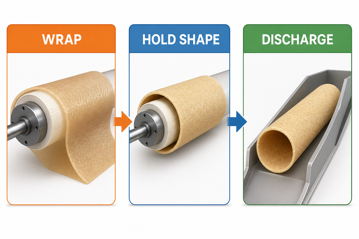
At the instant it touches the former, a newly wrapped wafer cannot be treated like a rigid tube. It must hold the wrapped geometry long enough to leave the forming zone without immediately opening. As the wafer cools, its mechanical behavior shifts toward the crisp, brittle state associated with the finished roll.
The risk of cracking or unrolling appears because the handoff must occur while the wafer can still bend yet can soon hold the wrapped shape.
State change, not a promised cooling line: “Cooling” here means that the formed wafer stiffens as it loses heat. The machine may retract a forming rod, release a clamp, eject a discrete roll, cut a continuous tube, or let the product enter a chute. Those are layout examples, not evidence that every machine includes a separate downstream cooler.
US6254916B1 describes an endless tubular wafer body cut into measured rolls that become crunchy and brittle while cooling. CN119073336A describes rotary cutting followed by collection in a chute. Together they show why forming, cutting, and discharge can be coupled in different ways.
How Do Sensors, Drives, and Interlocks Keep the Cycle in Sequence?
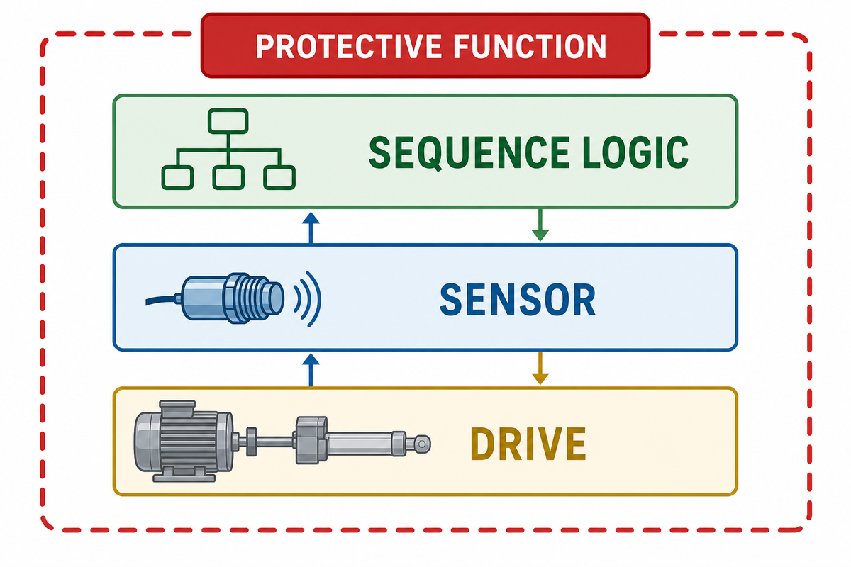
Automation comes from coordinated permissions and actions. Drives produce motion. Process sensors report position or condition. Sequence logic decides whether the next action is allowed. Protective functions constrain hazardous motion. These roles can share a controller, but they should not be described as interchangeable.
The main risk is to conflate those roles because a process-ready signal is not evidence that a protective function is satisfied.
| Control or signal type | Typical question | What it does not prove |
|---|---|---|
| Start permissive | Are the documented preconditions ready? | That every hazard has been removed |
| Deposit-position signal | Has the receiving surface reached the metering point? | That the delivered amount is correct |
| Heating-path feedback | Is motion following the intended process sequence? | That the wafer has reached a universal endpoint |
| Release-position signal | Has the surface reached its removal point? | That the sheet separated cleanly |
| Transfer permissive | Is the receiving path in the expected position? | That the hot sheet is undamaged |
| Forming-motion command | Which drive or actuator moves at the former? | That the formed geometry meets a product specification |
| Discharge-clear signal | Has the outgoing path cleared for the next handoff? | That downstream equipment is ready |
| Protective stop function | Must hazardous motion stop or remain inhibited? | That servicing energy has been isolated |
“One or more methods of machine guarding shall be provided.”
That rule addresses operating hazards such as points of operation, nip points, and rotating parts. The separate hazardous-energy standard covers servicing and maintenance. Neither citation proves that a particular machine meets an applicable requirement; that assessment belongs to the actual equipment, installation, task, and jurisdiction.
Are egg roll machines easy to use?
Routine operation can become straightforward after commissioning and training because controls present repeatable start permissions, status, and stop conditions. “Easy” never means unskilled, unattended, or safe to bypass. Operators still need machine-specific instruction on normal loading, guards, permitted adjustments, alarms, and emergency actions.
Recipe setup, validation, cleaning, maintenance, and energy isolation are separate responsibilities. Buyers should judge ease of operation from the actual interface, documented procedures, training, and task risk rather than from a one-button marketing claim.
Rotary vs Indexed Motion: What Changes Inside the Cycle?
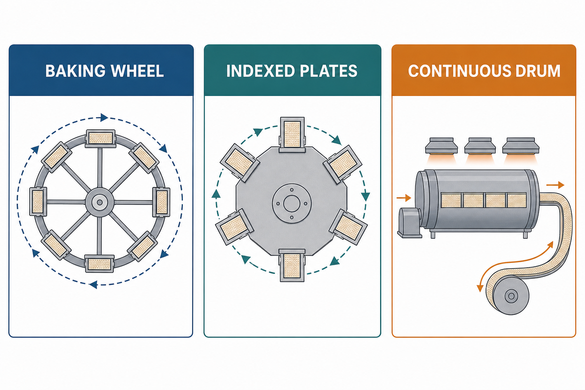
The six functions can survive a change in motion architecture, but their physical locations and timing references move. A rotary wheel or drum carries material continuously around an axis. A mould or plate system may advance through discrete positions or close at a defined arrival point. Neither layout is universally better.
| Architecture | Timing reference | Handoff pattern |
|---|---|---|
| Baking wheel | Angular position along one revolution | Coat, bake around the path, scrape, form, and cut |
| Moving or indexed moulds | Mould arrival, close/open state, or index position | Deposit at a receiving point, carry through heat, then open or release |
| Continuous drum and strip | Drum rotation and removal level | Peel a continuous strip into a winding gap, then cut the tube |
The first and third rows are documented examples in CN119073336A and US6254916B1. EP2105051B1 provides a mould-arrival depositing example for the second family. These sources establish design diversity, not a performance ranking, and this article does not use the comparison to recommend one layout. Procurement acceptance and supplier-comparison questions belong in the separate 12-point equipment acceptance checklist.
Follow One Batch Through the 6-Stage Deposit-to-Roll Timing Chain
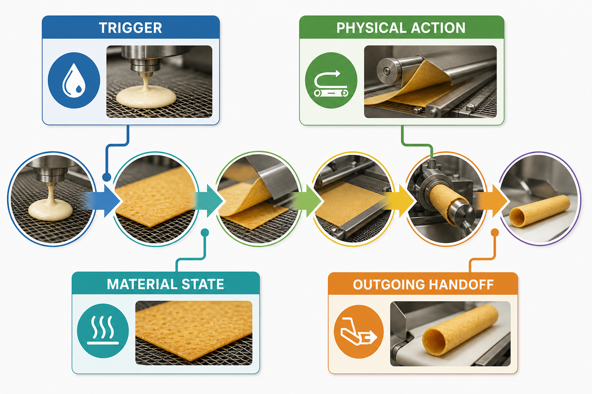
A timing chain is easier to audit when every row states four things: the trigger, the physical action, the material state, and the outgoing handoff. The table below is deliberately free of cycle-time numbers because the evidence does not establish a universal duration. The risk of a wrong reading is hidden overlap because one component can continue an earlier function while starting the next.
| Function | Possible trigger | Physical action | Material state and handoff |
|---|---|---|---|
| 1. Meter | Receiving surface reaches deposit position | A controlled flow or portion reaches the surface | Flowable batter becomes a placed thin layer |
| 2. Bake | Deposit complete; plate closes or surface continues moving | Heat and residence time build a coherent sheet | Wet layer becomes a hot baked wafer |
| 3. Release | Surface reaches removal position or plate opens | Blade, scraper, lift, or geometry frees an edge | Attached sheet becomes available to move |
| 4. Transfer | Free edge enters a guide or pick-up path | The wafer is aimed and carried to the former | Free hot sheet reaches rolling orientation |
| 5. Roll | Wafer reaches the forming point | Former and guide wrap and support the sheet | Flat sheet becomes a tubular body |
| 6. Discharge | Shape holds enough for release or cutting | Former retracts, roll ejects, tube cuts, or product enters a chute | Formed roll leaves for the next process |
Read across, not just down. Plate closure may continue Stage 1 spreading while beginning Stage 2 heat contact, a cross-stage effect documented in an open-access wafer study. A removal blade may perform Stage 3 separation and begin Stage 4 guidance, as illustrated in a continuous-drum patent. The model is valuable exactly because it records those overlaps, rather than concealing them behind a list of parts.
How Newer Controls Can Observe and Influence the Same Mechanical Cycle
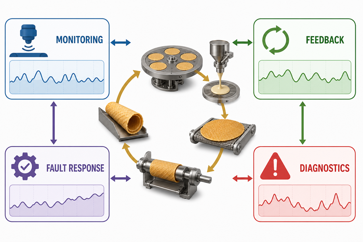
Current smart-manufacturing efforts go beyond showing status. Depending on the documented process, data and control can enable monitoring, feedback, optimization, diagnostics, fault response, or reconfiguration. Those can change how a process is watched and affected, but they do not eliminate the physical need to deposit, bake, release, transfer, form, and discharge the wafer.
The risk is overclaiming a generic capability because actual feedback, optimization, or fault response must be demonstrated for the machine being described.
| Physical event | Possible data or control role | Evidence source required before claiming it |
|---|---|---|
| Cycle ready | Start permission or inhibited state | Machine sequence and safety-function documentation |
| Surface at deposit point | Position status or deposit permission | Input/output list and sequence record |
| Deposit complete | Flow stop, plate closure, or travel permission | Control narrative and hardware description |
| Travel through heating path | Timing feedback or controlled drive motion | Validated operating logic and process evidence |
| Release position reached | Removal command or position confirmation | Sensor list and cause-and-effect record |
| Transfer path engaged | Handoff coordination or exception detection | Machine-specific sequence documentation |
| Forming motion complete | Drive status or next-step permission | Functional description and test record |
| Product discharged | Cycle reset, downstream handoff, or fault response | Interface record and actual equipment verification |
The NIST smart-manufacturing program mentions real-time control, optimization, diagnostics, and response to dynamic conditions. Its domain is manufacturing in general, not egg roll machines. A 2026 NIST roadmap also mentions advanced sensing, robotics, digital twins, and trustworthy operation as broader directions.
Food-manufacturing policy shows the same direction. China’s 2025 food-industry digital-transformation plan discusses digital management and adoption of key processes. This is a contextual cue only; it does not establish that UDTECH or any named machine has a specific digital feature.
Egg Roll Machine Working Principle FAQ
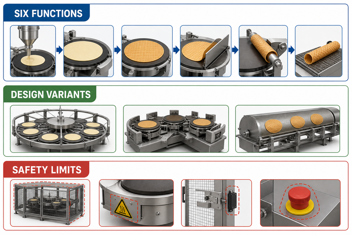
How does an egg roll machine work from start to finish?
An egg roll machine delivers batter to a heated moving surface, allows heat and residence time to form a thin wafer, frees the wafer from that surface, guides it to a forming point, wraps it into a tube, and discharges or cuts the formed roll into the discharge path. In turn, sensors, drives, and sequence logic coordinate those steps. The six labels indicate material changes; one machine component can be involved in more than one stage.
What are the main components of an egg roll making machine?
Component labels vary, so it’s more cautious to aggregate them by function: batter feed and metering, a heated plate, mould, wheel, or drum, a release device, a guide or transfer apparatus, a rolling or forming assembly, a discharge path, drives, sensors, controls, guards, and stop functions. A given machine may combine several functions into a single assembly or add modules that fall outside this process guide.
How does an egg roll rolling machine form the wafer?
The released wafer reaches the former while it can still bend. A guide corrects the position of the sheet, then a rod, mandrel, roller pair, or forming assembly wraps it around an axis. The overlap is supported briefly before the roll leaves the forming area or a continuous tube is cut. Several alternate motions are documented in patent records, so no single roller design should be seen as universally applicable.
Why must the wafer be rolled while it is hot?
The hot baked sheet can bend around the former. Cooling then moves it toward the crisp, brittle state expected of a wafer roll. Because the usable forming period depends on the product and machine, this explanation gives no universal temperature or number of seconds.
What is the difference between a baked-wafer egg roll machine and a spring-roll machine?
A baked-wafer machine turns batter into a thin heated sheet and rolls it while hot. A filled spring-roll system handles wrapper dough or prepared wrappers plus filling, then folds or closes the product for later cooking. Their starting materials, heat sequences, and forming mechanisms differ.
Do all automatic egg roll machines use the same cycle?
No. Automatic egg roll machines can share six material functions while using different timing references, release devices, transfer paths, forming hardware, controls, and guards. Rotary drums may combine operations continuously; indexed plates can perform them at separate positions. The cycle is a functional map, not a universal layout.
Keep the intent boundary clear: This guide explains the mechanism. Use the egg roll machine maintenance guidance for maintenance topics, and the configuration page for models, capacity, specifications, or an enquiry. Learn more about the team on the UDTECH company background page.
References and Sources
- CN119073336A — Fully automatic wafer roll machine (published Chinese application; the linked document names Guangzhou Yitong as applicant; no grant or current-rights claim is made).
- EP2105051B1 — Flexible depositing system and method (Nestec; one mould-arrival depositing design).
- US6254916B1 — Method and device for producing edible wafer rolls (Haas Franz Waffelmaschinen Industrie GmbH; continuous drum, removal, winding, and cutting).
- Butt et al. — Structure and mechanical response of baked and extruded confectionery products (Nestlé-supported research using samples made in a Haas single-plate oven; peer-reviewed baking-plate engravings (reedings) and material-structure evidence).
- Mayo Bayón et al. — A Wireless Portable High Temperature Data Monitor for Tunnel Ovens (peer-reviewed conveyor-oven monitoring and general baking-variable context).
- OSHA 29 CFR 1910.212 — General requirements for all machines (United States guarding reference).
- OSHA 29 CFR 1910.147 — Control of hazardous energy (United States servicing and maintenance reference).
- NIST — Smart Manufacturing Operations Planning and Control Program (general control, optimization, and diagnostic context).
- NIST — 2026 Roadmap on Artificial Intelligence and Machine Learning for Smart Manufacturing (current manufacturing context).
- China Ministry of Industry and Information Technology — 2025 food-industry digital-transformation plan (policy context only).
Patents describe particular designs and do not prove universal practice, commercial performance, or product conformity. General research and government sources are applied only within the limits stated beside each claim. Machine configuration and applicable safety requirements must be confirmed for the actual equipment and site.