Get in touch with UDTECH Company


Updated October 2026
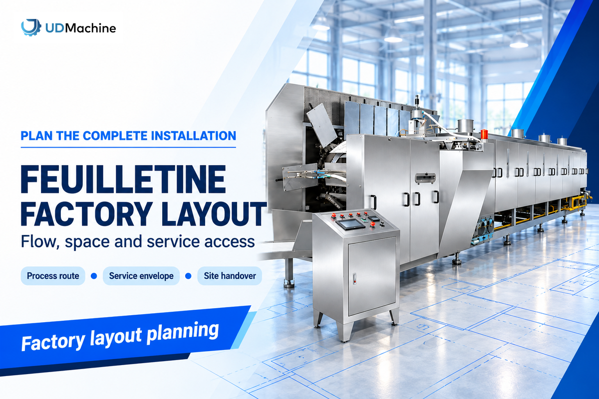
Feuilletine factory layout planning puts the production sequence, equipment service space and material routes onto one measured building plan. Start with batter preparation, baking, cooling, flaking and packing. Draw the actual equipment arrangement, trace how people, ingredients, packaging and waste move around exposed product, and reserve the service and material routes before walls and partitions are placed.
Planning reference
Equipment: UDTECH YT-10 baking unit. Process boundary: preparation through packed flakes, with each supplied module identified. Drawing output: a building plan with service envelopes, transfer points and assigned installation responsibilities.
A machine can fit inside a room while its cleaning trolley, opened guard or removal route does not. Good layout plans follow the flow of materials through these competing demands. Before choosing the arrangement that uses the least floor space, place the opened guards, removable components, cleaning trolley, packaging replenishment and waste collection on the drawing together, because counting the same space for incompatible tasks can hide the work that will stop the line.
Before approving the layout
- Separate the baking-unit body from the space needed to install and service the complete process.
- Compare straight and U-shaped arrangements using actual equipment interfaces.
- Review recipe, people, packaging and waste routes where they meet exposed flakes.
- Give the equipment supplier and local contractors the same drawing revision.
Map the process before drawing the room
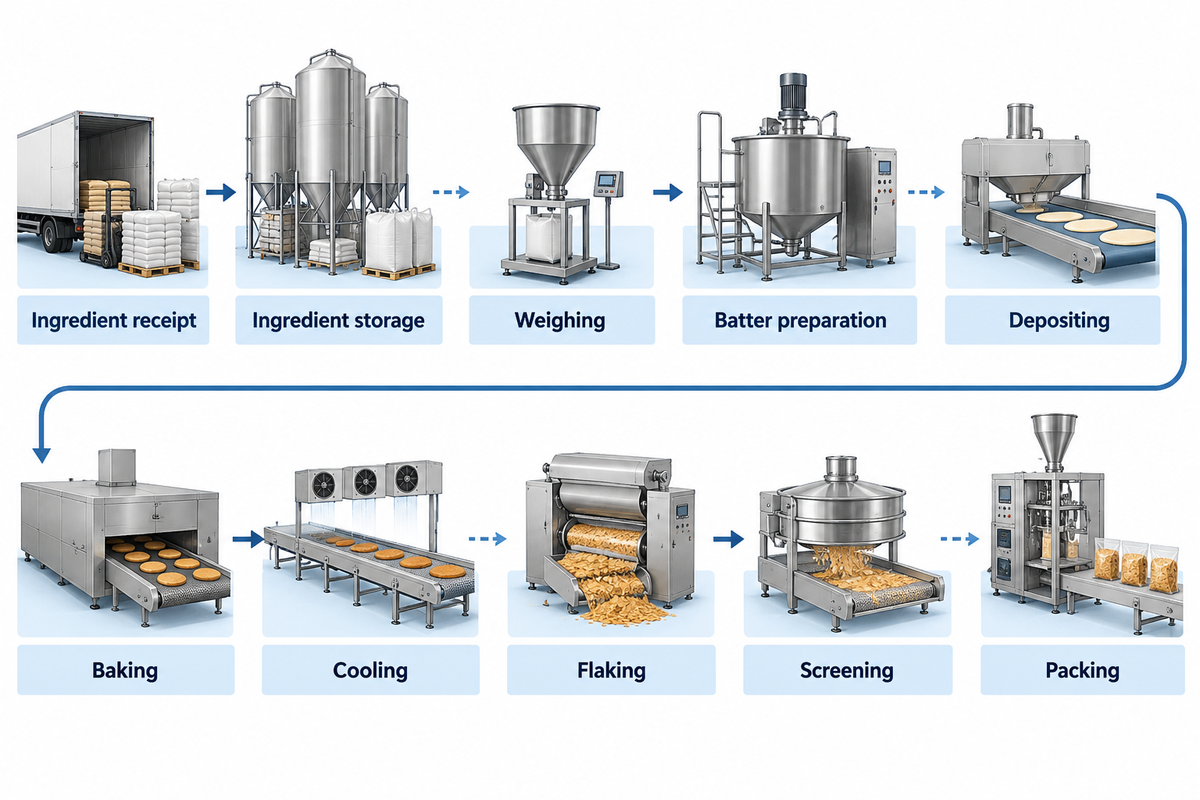
Draw the movement of ingredients from the incoming goods to sealed product and label the ownership and outlet of every stage. A feuilletine production line may mix supplied machinery with equipment that’s in the facility. The first drawing should show these interfaces so that the quotation and the factory plan describe the same operation.
There should be a connected route for the baked sheets to pass through the cooling step and the chosen flaking arrangement. These thin baked sheets need handling that differs from soft crepes folded or filled before further processing. Define the final flake specification and application before treating any generic bakery assembly line as a suitable model. The Industrial feuilletine process guide describes the product sequence in more detail.
| Stage | What the drawing must locate | Decision before approval |
|---|---|---|
| Ingredient receipt | Delivery door and inspection position | Keep incoming loads out of exposed-product handling. |
| Ingredient storage | Dry stores and recipe-specific locations | Allow replenishment without using production aisles as a warehouse. |
| Weighing | Ingredient issue and dust-producing tasks | Review the actual powders and recipe-change procedure. |
| Batter preparation | Mixing, transfer and cleaning location | Agree how wet preparation connects to the baker. |
| Depositing | Feed connection and operator access | Match the transfer to the selected machine. |
| Baking | Baking-unit body and service sides | Use the selected configuration drawing. |
| Cooling | Product path and surrounding activities | Keep exposed sheets away from incompatible traffic. |
| Flaking | Transfer geometry and collection point | Agree product height, containment and removal access. |
| Screening | Accepted flakes, fines and rework outlets | Assign a destination to each stream. |
| Packing | Packaging entry and sealed-product exit | Separate clean packaging from used outer cartons. |
How can the facility layout reduce unnecessary handling?
A facility layout can reduce unnecessary handling by putting connected process stages beside their actual transfer points and giving each material stream a specific outlet. Trace the movement of one batch from the issue of the ingredients to the dispatch of the finished product. A repeated return trip, temporary floor container or transfer across a busy aisle identifies a specific layout decision to change.
Record the reason for each transfer before trying to eliminate it. Carrying rejected product through the packing area is wasted handling, however short the conveyor. Judge the layout on the whole route, not on the length of one connection. Trace the fines and rework destinations before deciding how to reduce waste.
Size the installation envelope around the baking unit
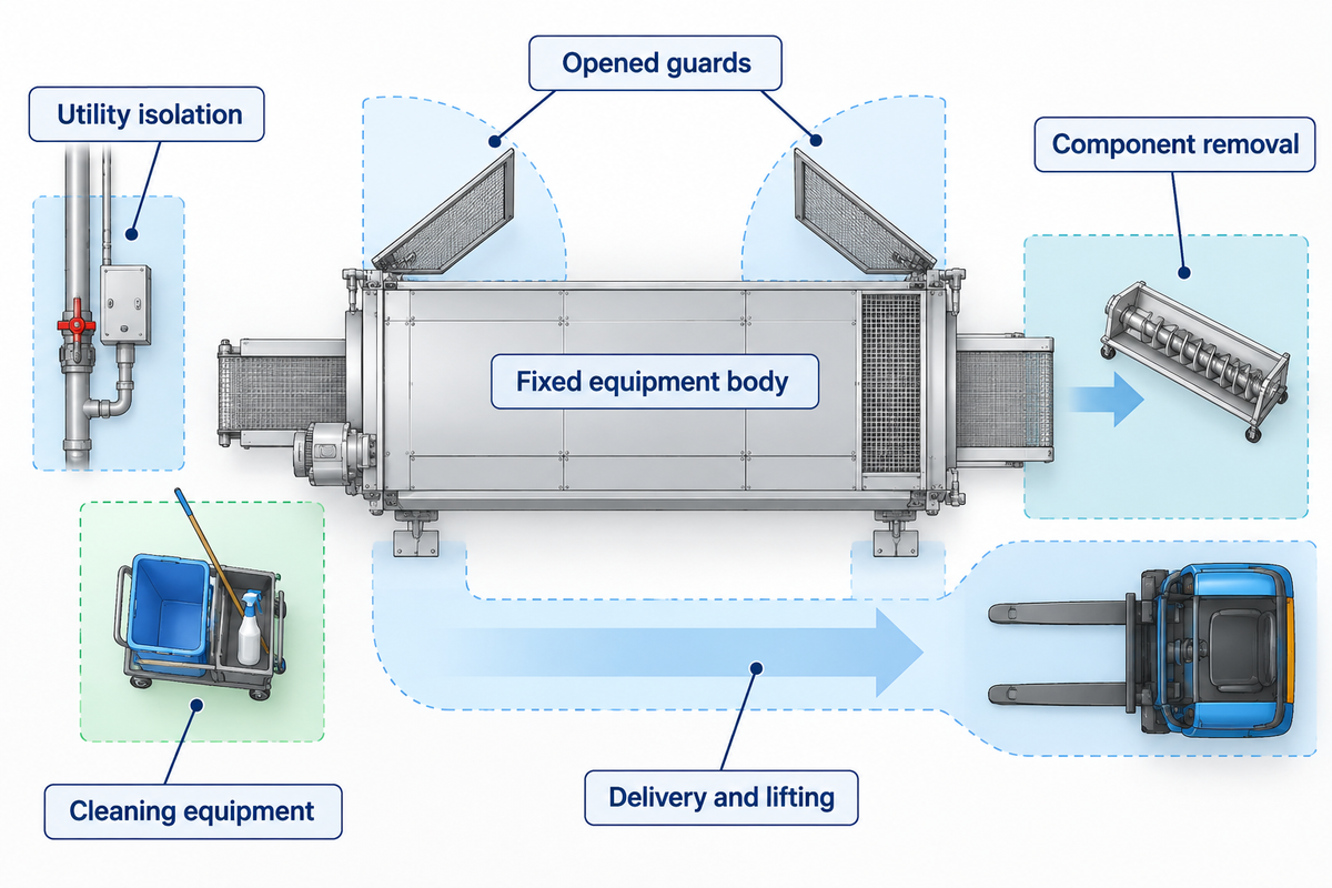
UDTECH publishes a YT-10 baking unit body which is 9.8 m long, 1.6 m wide and 1.9 m high. Its footprint is 9.8 m × 1.6 m = 15.68 m². The complete plant layout includes downstream equipment, opened parts, cleaning and service access, operating ways and the route followed to bring machinery into the building.
Keep the height as a separate input: overhead services, exhaust connections and lifting arrangements belong on an elevation drawing. Even with a generous factory floor, there may not be enough ceiling space to perform the required services and a different method may have to be used to install the equipment.
Use the Body-to-Service Envelope Check to transform the equipment outline into a usable space plan. Lay the following demands on the same drawing. The installed envelope is the combined space these tasks need; two access areas can overlap only when the tasks can share the space, for example because they never happen at the same time.
| Drawing layer | Conflict to test | Planning response |
|---|---|---|
| Fixed equipment body | A column falls inside the selected footprint. | Move the equipment or revise the selected configuration. |
| Opened guards | A guard swings into a permanent barrier. | Reserve its complete opening movement. |
| Routine inspection | The inspection side faces an inaccessible wall. | Reorient the unit or provide suitable access. |
| Component removal | A removable part cannot clear adjacent machinery. | Draw the removal movement and receiving position. |
| Cleaning equipment | A trolley must stand in the material route. | Provide a cleaning position suited to the task. |
| Operator movement | Normal work crosses a product transfer. | Change the work position or protect the transfer. |
| Material handling | Replenishment blocks the machine service side. | Reposition the issue point and delivery route. |
| Utility isolation | A fixed pipe covers an access panel. | Coordinate pipe routing with maintenance access. |
| Delivery and lifting | The shipping unit cannot pass the entrance. | Agree the delivery sequence and lifting method before dispatch. |
| Future equipment | Reserved expansion space is already used for storage. | Show the reservation and its permitted temporary use. |
A procurement team can use the table to analyze equipment layouts without adding an arbitrary percentage to every footprint. The dimension at the service side comes from the movement required there. Maximize usable production space after these task envelopes are drawn. The feuilletine baking equipment page provides the reference model and describes the supplied-scope boundary.
Choose a route, then test straight and U-shaped options
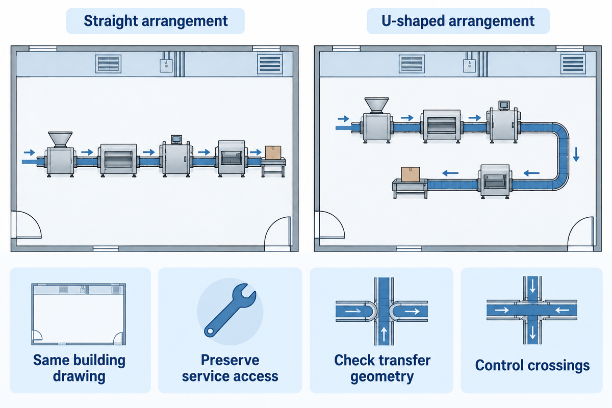
A straight arrangement suits a process where the actual transfers can run in sequence across the building; a U-shaped arrangement is worth testing if the available doors or downstream operations favor a return route. Select the shape after checking transfer geometry and access and crossing control. Same-wall receipt and dispatch don’t determine the equipment shape.
Compare both options on an identical building base drawing, with the same production scope and storage assumptions. Otherwise, the apparent winner may simply omit a cooling section or put its packing stock outside the comparison. Both route sketches should also preserve the cleaning and inspection access described by Cornell. Judge handling by the accepted product movements and the service tasks that interrupt them; the better arrangement is the one that balances both for the selected process.
Let’s take the existing workshop with loading doors on one wall and a column row in the middle. A U-shaped sketch could bring sealed product back to dispatch, but the return portion could be in the component-removal side of the baker. A straight line may preserve service access and also require a separate finished-goods route. So the trade-off is between two complete routes, not two nice-looking sketches.
To start comparing alternatives, decide for each crossing whether the two flows can share it at the same time or must be separated in time or by a physical barrier. Keep an unacceptable option next to the selected one and the reason for rejection. Simulation software becomes useful when real dimensions, movement rules and operating assumptions are available; a moving animation of incomplete equipment blocks adds little to the decision.
Separate wet preparation from exposed baked product
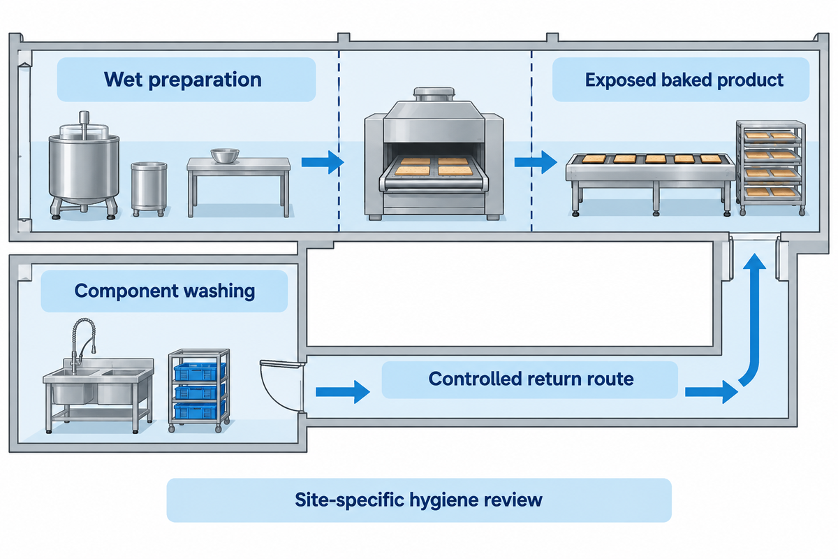
Place wet preparation and its cleaning activities in a manner that prevents water, splash and used equipment from coming into contact with baked product. Provide the desired separation of the product and cleaning activities. Walls, enclosed transfers and/or controlled openings serve a different purpose from painted lines on an open factory floor.
The European Hygienic Engineering and Design Group uses risk-based design principles to treat processing equipment and its manufacturing environment. Its public GL 8, fourth edition (December 2025), states:
“Entities (equipment and facilities) with poor hygienic design are difficult to clean.”
Mark the location where components are washed on the drawing, and mark the route the components take upon their return from washing. A component that leaves a dry area for wet cleaning must have a controlled route back to its dry location. The required arrangement is determined by the equipment cleaning method and the hygiene assessment.
Texture and food safety need separate acceptance criteria: a sanitation procedure that is acceptable for food safety may still expose crisp flakes to moisture during transfer. For product-side moisture exposure, use the separate guide to why feuilletine loses crunch; keep this plan focused on where those exposures occur.
The US Food and Drug Administration’s 2025 draft guidance for low-moisture ready-to-eat foods discusses sanitation programs, environmental monitoring and corrective action following pathogen contamination. It is still a draft, so treat it as technical background rather than a requirement. Include the sanitation and monitoring tasks in the room review, along with the product’s texture criteria.
Give people, packaging and waste their own routes
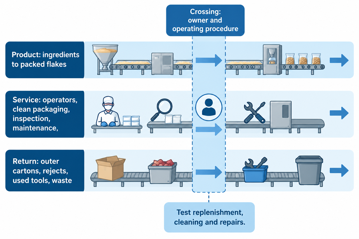
Map people and material movement by activity, then control the locations where those routes meet exposed product or clean equipment. The 3-Layer Route Test separates three kinds of route: product, service-and-supply, and waste-and-return. A crossing is a control point with an owner and a specific operating procedure.
Layer one tracks ingredients through accepted packed flakes. Layer two tracks operators, clean packaging, inspection and maintenance. Layer three follows outer cartons, rejected product, used tools and waste. Apply the same test during replenishment, cleaning and a stopped-line repair; a plan that works only during steady production leaves important work unplanned.
Changes in the recipe add another layer to these tests. The Canadian Food Inspection Agency’s (CFIA) June 5th, 2023, updated technical guidance, refers to mapping of ingredient flow, air movement, shared equipment, and staff traffic, to help identify allergen cross-contact. Use it as technical background for this drawing review, not as a legal requirement in the country where the plant is built. Assign rework to the permitted product route, identify recipe-specific storage, and include the cleaning changeover in the operating plan. The allergen rules of the country where the plant operates still need a local review.
For instance, if replenishing packaging brings used outer cartons through an exposed product area, then a separate position to remove used outer cartons can resolve the conflict. If the whole packaging machine is moved, it changes the service envelope and product route as well.
Make cleaning and component removal possible
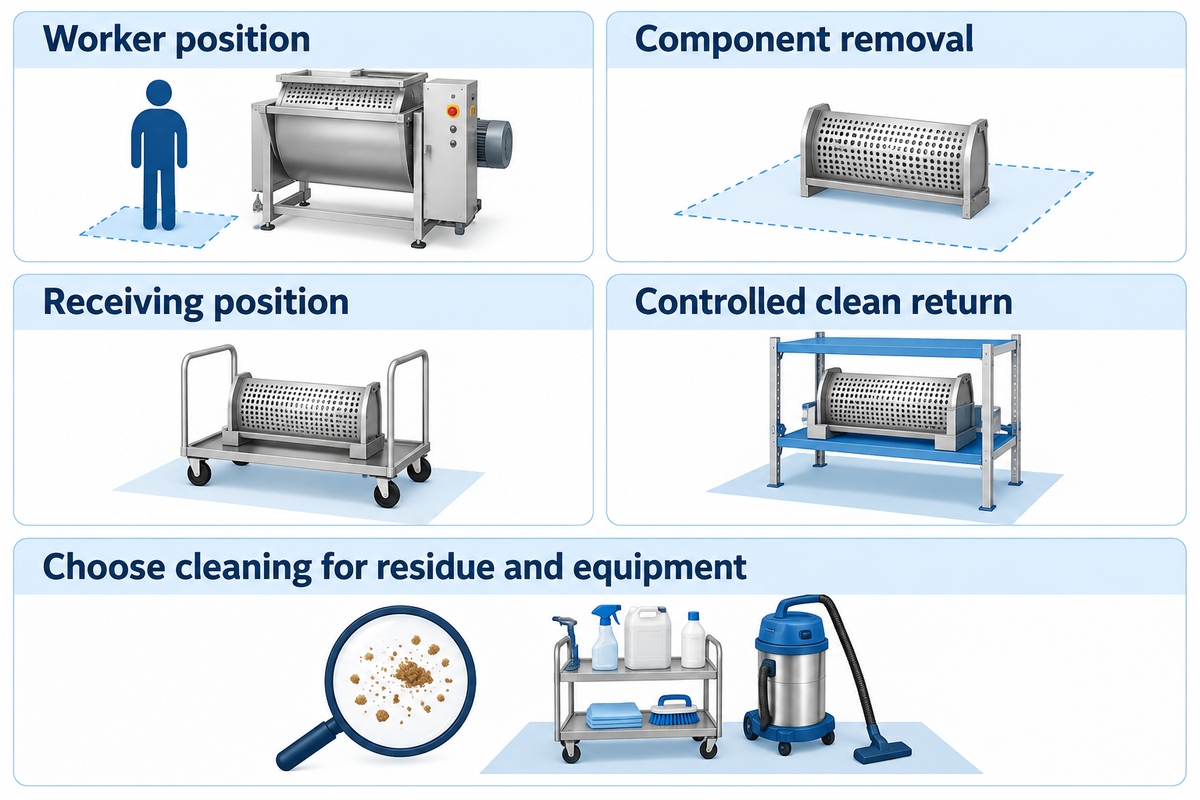
Access must be reserved for the actual cleaning, inspection and component removal tasks before adjacent walls or machines are approved. Cornell’s good-manufacturing practice resource states that cleaning and inspection access should be considered as equipment-layout considerations. This principle should be demonstrated by task. For example, show where the worker stands, where the component moves, and where the removed material is placed.
A well-designed layout provides for the maintenance function as well as the production function. When reviewing drawings, follow an opened guard, a removed component and a cleaning trolley for the entirety of their travel. Request that maintenance and quality personnel review the same sequence; their requirements may be different from the operator’s normal work position.
Methods of cleaning differ for various residues. Whether the residue is sticky or dry and powdery, the cleaning method has to suit both the residue and the equipment. A dry-product room isn’t necessarily assigned a dry-cleaning method just because the end-product is flakes of a dry substance. Choose a procedure that removes the actual residue and suits the equipment’s water tolerance, then review how moisture and retained material will be controlled when cleaned parts return to dry processing, following the scope of Canadian technical guidance and EHEDG GL 22.
When a wall makes a required task impossible, price the wall change beside the equipment change. This also helps avoid a layout that only looks space-efficient because routine work would require dismantling neighboring equipment.
Check heat, air and moisture at the interfaces
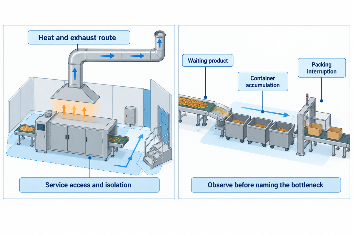
Coordinate the baker’s heat and utility connections with nearby cooling, exposed-product handling and packing activities. Provide access and isolation points for services, and show exhaust routes on the layout design plan. Size the building services from the equipment requirements, together with the local services designer.
For detailed utility inputs, see the utility-planning guide. A supply pipe crossing a removable panel, a service connection behind a fixed partition or an oven exhaust route through reserved expansion space is a layout problem even when the nominal utility supply is adequate. Include the raw materials in the dust review and the environmental conditions around exposed product in the room review.
Dust belongs in this interface review. Flour, sugar and other food powders can form explosive dust, so the review must also cover nearby ignition sources. Have the responsible expert assess the actual materials and process, including powder handling, collection equipment, housekeeping and the relationship to the baking area.
The cooling-to-packing path is a useful constraint map. Identify where sheets wait, flakes are exposed, containers accumulate, and packaging stops interrupt upstream handling. Record waiting time and accepted output during the agreed trial. Locate a bottleneck through observation rather than assuming the longest conveyor is the limiting component.
Accept the cooling arrangement with the product trial and transfer design. Cooling acceptance is covered in the separate article on cooling before flaking.
Price the building work beside the equipment
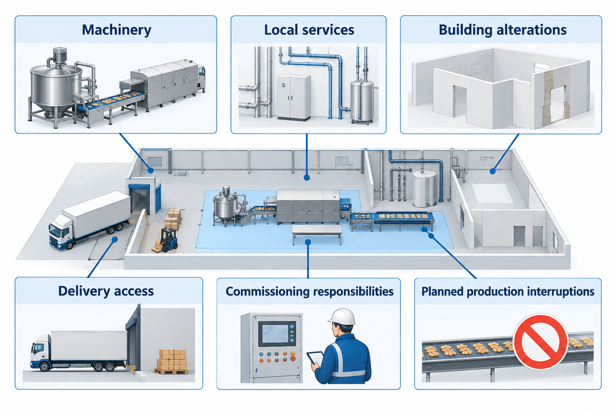
Compare quotations on the same installed scope: machinery, local services, building alterations, delivery access, commissioning responsibilities, and planned production interruptions. A competitive equipment quotation may leave more work to the factory. Keep the missing scope visible as a separate cost item rather than treating it as a saving. Resolve a scope error before comparing the totals, and carry the agreed quality and consistency criteria into both acceptance packages.
Consider two retrofit options for a packing room: the first keeps packing where it is and adds a transfer from the new baker; the second moves packing next to the new baker. The first option may retain the existing working area; the second may simplify material flow but require more building work and changeover planning. Finance needs installed quotations for both. Quality needs the proposed exposure and cleaning controls. Production needs an agreed interruption plan.
Use a common cost boundary: equipment supply, freight and handling, Local installation, building work, agreed trials and interruption costs. The EHEDG public hygienic-design summary covers designing, constructing and installing equipment and facilities; include the corresponding building and equipment work when agreeing the installed scope. Allocate each item only once. Separate the equipment already owned from the new purchase, for the comparison to remain valid. Mark any item that has not yet been quoted or verified as open, rather than filling the gap with an estimated installation price or an assumed productivity gain.
Put supplier scope and site readiness on one drawing
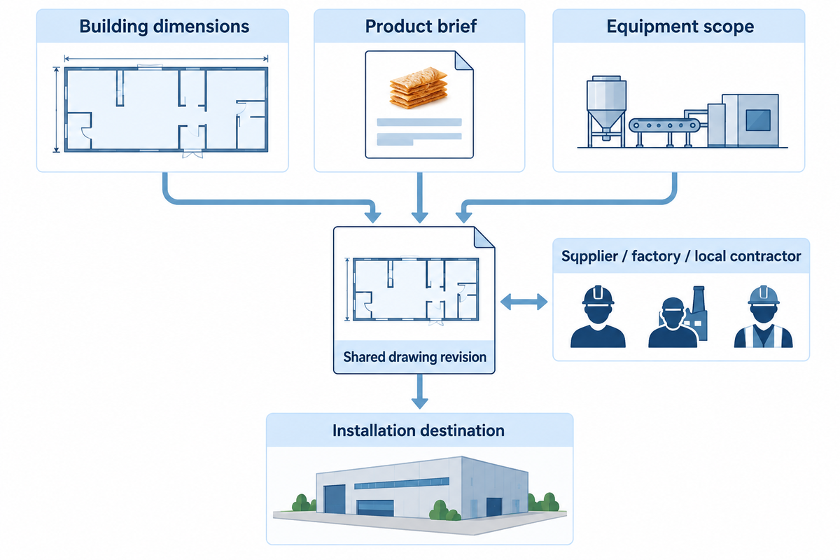
Send the manufacturer a building plan showing the dimensions of the building, product brief, and equipment-scope list with a shared revision reference. Identify the columns and doors, usable height, existing services and the agreed production sequence. Assign each of the interfaces to the supplier, the factory or a named local contractor, so that a drawing change reaches the person who will implement it.
Keep the product brief focused on the specific requirements of the product (e.g. flake form, recipe or sample, daily accepted demand, operating pattern, downstream stages, etc.). If the project is for a different product (for example, a filled product or topping application), that also needs to be described separately. This could impact the way the product is handled and stored, and the changeover time for cleaning.
A first rough sketch of a floor plan can be done using a free online tool. When designing the production arrangement, replace generic machine blocks with configuration drawings before approval. Software can help with alternative routes, but the factory and supplier need to agree on specification and installation responsibilities. Put the local building, fire, occupational-safety and food-business approval responsibilities for the installation country into that handover.
Send UDTECH your building sketch and product brief with the process stages you want supplied. Include the installation destination and the local team’s responsibilities so the quotation can address the equipment interfaces and service scope.
Plan cleaning access into the next retrofit
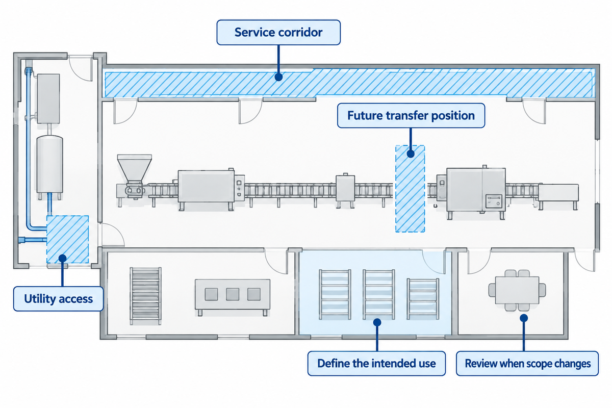
For future flexibility, secure access that remains usable when production changes. Set aside space in proximity to critical components and transfer points that are likely to be impacted by a different product, packing format or downstream module. Show these set-asides on the drawing so that current storage configuration doesn’t restrict potential future storage and routing.
Check which edition of each guideline you are using. EHEDG’s general hygienic-design GL 8 public page identifies a fourth edition from December 2025; the dry-particulate GL 22 page identifies a second edition from March 2014 and notes revision work. Equipment hygiene certification is separate from the approval of a complete factory.
Food Engineering’s October 2026 feature The State of Food Manufacturing in 2026 reports that spending is expected to stay focused on brownfield upgrades and line expansions, and that hygienic design and sanitation are at the forefront of equipment-purchasing and plant-design discussions. For a feuilletine buyer, the practical point is to review the building constraints early, while the line layout can still be changed.
A good expansion plan keeps a service corridor, a future transfer position or access to a utility connection free. Define the intended use of each reservation and the criteria for re-evaluating it. A future large scale expansion will still need a fresh equipment and building review; the current drawing gives that review a clearer starting point.
Frequently asked questions
Can a free floor-plan template be used for the first equipment discussion?
Yes. A free template can show doors, columns and existing services for the first discussion. Add measurements and identify the drawing revision. Replace generic equipment symbols with the selected configuration before approving the installed arrangement. Include photographs of restricted entrances and overhead obstructions beside the sketch so the supplier can relate the measured building to the delivery and service routes.
Can a second product share the same feuilletine workshop?
Compare the recipes and operating tasks together.
Sharing can be considered when the product, ingredient, allergen, cleaning and traffic arrangements work together. Review shared equipment and rework as well as room space. Agree the required changeover and separation before committing to the shared workshop. List the ingredients for both products, the shared contact surfaces and the cleaning sequence on the same review sheet. Include packaging and labels in the changeover discussion. A room that fits both equipment outlines can still have conflicting replenishment or waste routes during a product change.
When should the supplier visit the site?
Resolve site constraints before final approval.
Arrange a site review before layout approval when measurements and photographs leave delivery access, services or retrofit constraints unresolved. Define what the visit must settle and which local contractors need to participate. Bring the current drawing and responsibility list so the visit ends with recorded decisions rather than a second set of informal assumptions.
Should expansion space be left inside the production room?
Reserve a defined future use.
Reserve space where the expected additional module can connect without taking away required operating and service access. Show its intended equipment, interfaces and access route on the drawing. Reassess the reservation when the product or expansion scope changes.
What should be approved before equipment is shipped?
Align the equipment, building and responsibility drawings.
Approve the selected configuration, transfer interfaces, service access, delivery route, utility connections and responsibility list. Record remaining local works and the agreed acceptance conditions. Use the same revision for the supplier, factory and installation team.
The YT-10 dimensions come from UDTECH’s published specifications. The route tests in this guide are planning aids; the project engineer and local team remain responsible for site-specific design and approvals.
References & Sources
- UDTECH: Feuilletine production equipment, YT-10 parameters and supply scope.
- Cornell Dairy Extension: Good Manufacturing Practices, educational guidance.
- EHEDG GL 8: Hygienic Design Principles, public summary, fourth edition, December 2025.
- EHEDG GL 22: Dry particulate materials, public summary, second edition, March 2014.
- Duane Grassmann: Hygienic Zoning in Food Manufacturing Factories, 2019 technical article.
- Canadian Food Inspection Agency: Food allergens, gluten and added sulphites.
- UK Health and Safety Executive: Preventing dust explosions in the food industry.
- US FDA: Draft guidance on sanitation programs for low-moisture ready-to-eat human foods, 2025 draft.
- Bonna Cannon: The High Costs of Saving Money, March 2026, capital-project risk discussion.
- Food Engineering: The State of Food Manufacturing in 2026, October 2026.